Thursday 29 December 2011

Front Lighting

The IVA test requires that the front indicators are no more than 400mm from the outside edges of the car.  On the Avon this would be measured in from the rear wheel arches (being the widest part of the car).  The rear arches are 1750mm in width so the indicators need to be no less than 950mm (1750 - 800) between their outside edges.  As with most sevens the indicators needed extending on stalks.

I found a plastic waste overflow pipe at B&Q which is the perfect fit to hold the motorcycle indicator units.


To create a fixing to the nose cone of the car I used a 22mm copper pipe blanking cap with a M8 bolt.  An 8mm bolt was used as this is the same as the indicator unit bolt.  The centre of the bolt was drilled out to allow the wires to pass through.  A length of rubber sleeve was used inside the bolt to prevent chafing on the edge of the hole.

As well as using glue a couple of 3.2mm rivets were used to lock the bolt in place and prevent it spinning when tightening the nut.  Finally, prior to fitting, a quick coat of black paint was used to cover the copper and rivets.


To allow more clearance on the cycle wings I've changed from the 5 3/4"  light units to the smaller 4" Dominator motorcycle units.  Being smaller they should reduce drag (a little) and boost the top speed (a little).

The wires needed extending and protective sleeving added.  The colour scheme for the wires was very bizarre.  I had to trace each one to the bulb holders to work out what was going on.  After the bullet connectors were attached I labelled each one to prevent future confusion.


Being a motorcycle light the Dominator has a flat beam pattern, with no kick-up to the left.  This is fine for the IVA test, but to help it pass the MoT the light unit is best rotated a few degrees to give the required kick-up.  To do this a second locating cut-out was filed, to the right of the original one.  This causes the whole light unit to be rotated anti-clockwise when viewed from the front of the car.


Front indicators and headlights mounted and wire in.  I'll replace the bullet connectors with soldered connections after the IVA test.  I've ordered some proper two pin connectors from Ebay for the front indicators.  This will make it easier to detach prior to removing the nose cone.


I had some black card handy in the garage so I thought I'd use it to check the beam patterns.  Here is the dipped beam.  Hot spot in the centre and kick-up to the left.  Hopefully good enough to please Mr (or Mrs) MoT tester.


And here is the full beam.


These are small light units and are mounted quite low.  As such their beam will be masked partly by the front cycle wings.  This should not be too much of an inconvenience as they will really only be used to get home around dusk.  I don't plan to be making too many long distance trips at night.

Monday 19 December 2011

Seats and Harnesses

Intatrim Ranger seats have been installed in the car along with the Tiger provided harnesses.  I decided not to opt for colour coded piping on the seats as I think there is already enough contrast with the red harnesses and red detail line on the wheel rims.  Also, I was a bit worried that light coloured piping on the seats would quickly discolour.  That said I'll have to make sure only clean hands handle the red harnesses.


To mount each seat four M8 cap head bolts were used with nyloc nuts.  Bolting through each of the two lengthwise chassis rails and fitted with load spreading washers inside the seat and underneath the car.


Friday 16 December 2011

Interior Trim

Originally I was going to go for the 'stripped out racer' look, but in the end I changed my mind and bought the interior trim set from Tiger.  This consists of a centre tunnel cover, carpet for the rear bulkhead, full length fitted floor mats, gaiters, aluminium and vinyl for the outer cockpit sides and carpet panels for the forward tunnel sides.

As I have the Rally Design gear remote I needed the hole in the tunnel cover for the gear lever to be further forward than normal.  I posted Tiger a paper template and they made up the tunnel cover to fit.

First job was to cut the aluminium side panels to size.  Once one was trimmed correctly it could be used as a template for the other side.  A piece of vinyl was cut and attached using contact adhesive.


The end result has turned out quite professional and looks really good in the car.  The panels themselves were fitted using black pop rivets.  A little silicon sealant was added on the runs between the rivets.  The idea here is to try and minimise any vibration of the panel when the engine is running.


With the carpet glued, using spray carpet adhesive, to the rear bulkhead and all other trim items in place, the cockpit starts to look really nice.  I need to get an angle welded in the gear lever (to clear the dashboard) before I fit the gear lever gaiter.


Next will be fitting of the seats and harnesses.

Saturday 3 December 2011

Rear Lighting

All fitted, wired up and tested.


Some of the wiring could be attached to the chassis tubes, but inside the wheel arches there is nothing to attach the wires to.  Some Grip Fill was used to glue clips to the inside of the wheel arches and then cable ties could be used.  Sprial wrap was then added to all wires to prevent chafing, particularly where the wires pass through the fibreglass.

As the fog light needs to be vertical for the IVA test I used one of Tiger's fibreglass 'wedges'.  I didn't need to use them on the rear light clusters as my light units are tapered at the back.  To mount the wedge I made up a small bracket.  I made sure the holes in the bodywork are the same spacing as on the fog light until, so in theory I can attach later without the 'wedge'.


Tuesday 22 November 2011

Cycle Wings

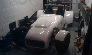
After the bonnet the job I was least looking forward to was fitting the cycle wings.  It did indeed turn out to be quite involved.

First off I needed to clear the threads in the front uprights - these were rusty and also had some paint in them.  I hadn't realised when renewing the uprights that these threaded holes would be needed.  A second hand 8mm tap from a local tool shop did the job easily.

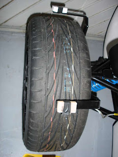
Spacer tubes need to be cut to mount the cycle wing vertical arms the correct distance from the tyres.  This is a bit of trial and error and I found it easiest to use washers to calculate the length prior to cutting the tubes.

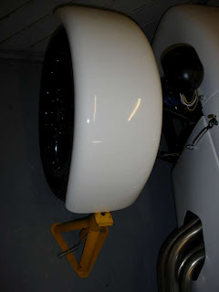
With the stays mounted in the correct position I could start to fit the cycle wings themselves.  They don't just bolt on unfortunately.  The horizontal arms of the stays need to be bent up into the curvature of the cycle wings.  To work out how far to bend them I tried spacers of different thickness.  A couple of pencil rubbers turned out to be perfect for the job.


Then the stays were bent in the vice, ensuring that the upper part remained parallel with the tyre.  Due to the bending of the stays some of the powder coating flaked off.  Some Hammerite was applied to prevent rusting.


The cycle wings were then trial fitted using an axle stand as a height reference.  The current IVA manual states that the cycle wings must extend at least 50 degrees to the rear and 30 degrees to the front.  The rear was nearly 90 degrees so that was okay.  The front was harder to measure.  In the end the geometry of the wheel came to the rescue.  There are 12 spokes.  360 degrees divided by 12 equals 30 degrees per spoke.  With one spoke vertical I could easily determine that I had about 45 degrees coverage to the front.


A length of bicycle inner tube (700c x 23) was pulled over the horizontal arms to protect the fibreglass from the metal edges.  Holes were drilled in the cycle wings and stays and then dome head bolts used to secure them together.

19mm holes were drilled to accommodate the LED side repeaters.  I had to be careful here as it is quite close to the edge and I didn't want to split the cycle wing.  The repeaters are mounted by inserting the rubber collar into the hole and then pushing the light through, making sure the 'TOP" marking was uppermost.  Due to the curvature of the cycle wing shoulder the rubber did not want to sit fully flat with the (curved) surface.  A little persuasion from Mr Super Glue did the trick.


Finally, the wiring for the side repeaters was extended to reach the inside of the car.  This was cabled tied to the cycle wings stays and under the cycle wings cable tie mounts were attached using Grip Fill.  Before fitting the side repeaters I tested them on the car battery.  They are reassuringly bright.  One oddity is that the black lead is not negative, but positive!  White is negative.

In the end I am quite pleased with result, but the cycle wings are quite a lot of effort from start to finish.

Monday 21 November 2011

Exhaust Clamp Tested and Rad Fan Switch Changed

Ran the engine again, this time with the silencer clamped to the cat pipe.  No leaks, so that job is done.

The radiator fan switch supplied by Tiger activates at 84oC.  This is a bit low for the Zetec on fuel injection so I always thought that I'd have to change it over to the higher setting.  Anyway, when I looked at the higher setting it was about 147oC so obviously no use!  I bought a replacement switch (Intermotor 50102 - for Peugeot 205/Citroen BX C15).  The lower setting comes on at 93oC and goes off at 88oC.  The higher setting is 97oC/92oC.  I installed it on the radiator and checked it in operation.  It seems to work okay.

As I have no thermostat installed I need the fan to operate at the correct temperature.  While running the engine with the car stationary the Tiger ali radiator seems to be very efficient at cooling.  I'll have to see how it performs when the engine is working harder on the road.  I may have to watch out for over-cooling, especially in the colder months.

Thursday 10 November 2011

Bonnet and Nose Cone Finished

Finally after much drilling, filing and swearing I've finished fitting the bonnet and nose cone.

The nose cone needed some cut-outs making for the lower front wishbone as well as the steering arm.  Bolts were added on each side and one underneath to mount it to the chassis.  I used epoxy to add a washer to the outside of the body around each hole.  This tidied up some rough edges (where the fibreglass started to split due to it being thinner in certain parts) and also spreads the clamping forces more evenly.  The lower bracket had to be extended to reach the lower part of the nose cone.  I think this is due to the fact that the nose cone sits slightly forward of its normal position to accommodate the Tiger alloy radiator, which is already inclined to the maximum.

With the nose cone in place this provided a reference for the bonnet.  This had to be cut quite a bit, very carefully, at the scuttle end.  In its natural position there was the usual huge gap on the drivers side, between the bonnet and the body side panel - maybe 25mm or more at the scuttle end.  I evened this up and now I have a small, but even, tapered gap each side.  The only down side is that the bonnet is trying to rotate back to its natural rest position.  This causes the front of the bonnet to rise up where the inlet bulge is.  This wouldn't be so bad on the version of the bonnet without the bulge because the spring clamps would pull it back down.  However, this is not the case with the asymmetric bonnet that I need to house the throttle bodies and air filters.  Hopefully it will settle after being clamped in position for an extended time.  If not, I might have to look at other solutions.  Possibly a couple of dowels and locating holes between the bonnet front and nose cone rear.  Anyway, I am glad this chore is over.


Tiger has made a good job of reworking the main body tub.  It is a big improvement over the previous version.  It is just a shame the bonnet and nose cone are not yet up to the same standard.

Self tapping screws were sprayed with satin black Rustoleum paint and used to fix the grille to the nose cone.


Wednesday 9 November 2011

Exhaust Clamp

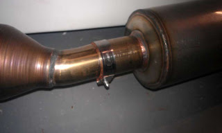
Prior to the second engine run I tried renewing the joint between the collector and the silencer with high temperature silicon sealant.  Unfortunately, this did not hold either.  So I bought an exhaust clamp from ebay, which I think is normally fitted to motorbike silencers.  I avoided the normal chunky u-bolt type clamp as this looks a bit clumsy and has more sharp edges to cause radius issues at IVA test time.

To make the join I first cut a 30mm slot on each side of the end of the silencer pipe.  Then aided with some more silicon sealant I clamped the collector and silencer together.  All seems good, but I'll only know when I next run the engine.  Fingers crossed.


Sunday 30 October 2011

Alternator Problem Solved

I didn't have a charge indicator light for the dashboard (digital dash has a voltmeter and a low/high voltage light).  Without this in the circuit the rectifier in the alternator does not send a charge to the battery.

With the light connected the alternator worked perfectly.  It's nice when problems are fixed easily (and cheaply).

Here is another video of the car running.  Apologies for the terrible sound quality from the mobile phone.  It is much, much better in real life.


Saturday 22 October 2011

Engine Start

I finally ran out of excuses not to start the engine.  So with a full tank of fuel and a fire extinguisher ready it was time to turn the key.  Unfortunately the battery died before it properly fired.  There is not enough power in the small race battery for extended cranking, so an hour's top up battery charge was needed.

Attempt number two, and she started straight away!  Here is the video:


I had hoped for a longer recording, capturing me driving very slowly backwards and forwards, but the video camera battery died prematurely too!

You can see smoke coming off the exhaust headers.  This cleared after a minute or so.  The engine was run until the fan cut in, at about 84oC, on the lower setting.  I'll try it again later on the higher setting.

There a couple of issues to sort out:

1.  The alternator (new from Tiger) is not charging.  I'll need to investigate this one.
2.  The high temperature silicon sealant holding the silencer to the collector partly melted and exhaust gases were seen escaping.  Hopefully it is just settling into its rest position and a re-application should keep a good seal.

Overall though I am really pleased.  Now I can get on with finishing the bonnet fitment (joyless task) and then concentrate on fitting the interior trim and seats.

Monday 17 October 2011

Dashboard

I am using the black GRP dashboard provided by Tiger.  Some people have fixed this on with screws, others with adhesive.  I wanted the clean looks (without screws), but without the permanence of adhesive.  I decided in the end to use regular clear silicon sealant.  My thinking is that it will hold the dashboard firmly, but can be removed later, if needed.  Perhaps by using a very thin long blade.  That technique may damage the dashboard, who knows.  Hopefully I won't need to find out.

I am mounting the digital dash (nearly) flush into the dashboard itself.  A template was cut for the hole required in the dashboard.


Hole cut in dashboard prior to sticking the dashboard to the body shell.


 Same size hole made in the body shell behind the dashboard.


A bracket to hold the digital dash at the right 'depth' was fabricated out of aluminium strip.  This was glued to the back of the dashboard using two healthy blobs of epoxy resin.  Seem to have held very well.


The dashboard had to be filed a bit to get the correct profile to match the scuttle.  I then took a few more millimetres off all round.  This allows a little space around the edge that I will glue some rubber trim on to for IVA.  I've tested a short length, made from the round part of P-trim, and it looks quite smart.

A second bracket was made to brace the lower part of the dashboard - to stop it flapping around.  Once the digital dashboard was mounted the switches were installed for the headlights, etc. Powered up and everything still worked!


Saturday 15 October 2011

Lamda Sensor

Simple job to fit the lamda sensor in the exhaust collector.  More difficult to complete the wiring.  The plug needed to be cut off as it is too big to go through a reasonable size hole in the body work.  Also the wire is way too long.  Only problem with re-soldering the lead is that the wires seem to be coated in something that prevents solder from taking.  I used a needle file to rub the coating off and expose the copper strands within.  Then it was a simple job to solder and make good with heat shrink sleeving.


Friday 14 October 2011

Raising the Height of the Engine

Tried to fit the air filters on to the throttle bodies.  The rear filter fits, but the front filter fouls on the upper chassis rail.

A 5mm space plate was inserted between the engine mount rubber and the chassis.  There is now 2 or 3mm clearance.  Should be enough as the engine shouldn't rock much with the firmer rubbers.


Tuesday 11 October 2011

Exhaust Fitted

Bracket made up to mount the silencer, painted with Hammerite and bolted through one of the steel chassis plates.

To fit the exhaust I used a high temperature silicon sealant (PRO SEAL RTV Silicone Instant Gasket RED 85g Hi-Temp) - it is flexible so won't crumble like exhaust paste and clog the catalyst.  Also it is supposed to be safe for use on lamda sensors.


Next to do is installation of the lamda sensor.

Thursday 29 September 2011

Exhaust Welding Completed

Got the welded exhaust parts back from Tiger.  Looks like a good job and after a trial fit the alignment still seems to be correct.  Will fabricate a bracket for the silencer next and get the exhaust fitted.


Thursday 22 September 2011

Cooling System - Mark 3

When previously installing the Tiger alloy radiator I re-used the 'puller' fan that I had bought for the Polo radiator.  This meant that the radiator could not be angled back fully all the way to the upper horizontal chassis rail.  Now that I'm able to trial fit the nose cone I can see that the top of the radiator is not low enough.  Time to replace the 'puller' type fan with a 'pusher' type.


With the radiator angled all the way back to the chassis rail the nose cone now fits properly.

The water rail was attached to the side chassis rail.  A dab of Sikaflex and a rivet at each end have made a strong mounting.


Tuesday 20 September 2011

Fuel Filler and Tank Vent Valve

To comply with IVA requirements the cap needs to be tethered to the fuel filler itself.  I copied the idea from the Carbuilder Solutions Catalogue, i.e. brass picture frame wire and cut down crimp terminals.

The cap did need dismantling first, but at least there are two holes available to take the wire and a handy recess to hide the crimp connector in.


With the cap reassembled ready for installation on the car.


Fuel filler hose connected up and all mounting bolts tightened.


I was a bit worried that the two bends required might be too tight or that the pipe might foul on the boot box molding altogether.  In the end it does not seem too bad and all being well the fuel will flow easily down the filler pipe and the air back up.

Next, time to fit the (not cheap at all) fuel tank vent valve.  This allows air in to the tank as fuel is used.  It also allows air in or out of the tank for expansion/contraction due to temperature changes.  Most importantly it does not let fuel flow out when inverted, i.e. when the car is upside down after an accident.  I think this is all done by a clever arrangement of two ball bearings and probably a spring or two.  The valve has to be fitted with the rubber o-ring uppermost.


That's the fuel system complete and ready for service.  Just need to complete the exhaust before the first engine start can be attempted.

Monday 19 September 2011

Cutting the Exhaust Pipes to Fit

Before getting started on this I realised that the lamda sensor boss was missing from my Webcon Alpha Pro4 kit.  I called Webcon, and as before, they were extremely helpful.  A replacement was posted first class and with me the following morning.


The various exhaust components were fitted together.


Problem was that the curved pipe between the cat and the silencer would not have enough metal showing.  This is a problem as where the bend is in the pipe the profile changes from round to oval(ish).  This is okay where the pipe is to be welded to the cat, but would not be okay where it is to be push fitted into the silencer.  To attempt to solve this the silencer was moved back a little, but there is not much room to play with as it is already near to the rear wheel arch.  In the end I removed about 25mm from the end of each exhaust header and this allowed just enough of the curved pipe to be showing.  The curved pipe was cut to the final dimensions and everything assembled.


All permanent joints were marked up for alignment ready to post to Tiger for them to weld, including the installation of the boss for the lamda sensor.


Tuesday 13 September 2011

Cutting the Hole for the Exhaust Headers

Before the body work was fitted a template was created out of pieces of card.


Copied to card a larger piece single.  Reference point was marked to ensure it would be in the right location on the chassis (measured from the upper wishbone bolt and top of the upper chassis rail.)


Checked on the chassis with the exhaust headers in place.


Used as a template after the body work was fitted.


Marked out using a chinagraph pencil (already learnt that even wipe clean whiteboard markers will not come of white fibreglass!).


First whole cut (actually drilled and filed).


And exhaust headers trial fitted.


The pipes were a tight fit and so the hole was opened up some more, whilst trying to ensure an equal spacing all round.


After removing the headers, refitting and tightening fully, the pipes were lower than before so a little more had to be cut off the bottom and rear.  Hopefully the gap above the pipes is now not too wide.  Maybe later on I'll make a metal trim to hide any sins.