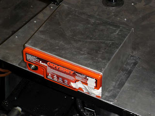
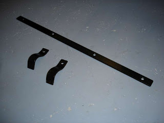
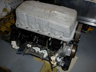
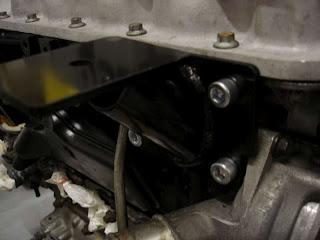
Spent a few spare minutes (hours) fabricating a bracket for the lightweight battery. The first attempt was very good, but turned out to be too large - I'd allowed a bit too much metal for the bending of the angles. Effort number two I would rather not talk about. Third time lucky. Will fix this to the battery tray later with wing nuts to allow the removal/refitting of the battery.
This blog documents my Tiger Avon kit car build project. The Tiger Avon is a Lotus 7 inspired car, using donor parts mostly from a Ford Sierra. My car is powered by a 2.0 Zetec engine from a Ford Focus.
Friday 20 May 2011
Polo Radiator Fitted
Some simple brackets made up from 5mm steel strip. B&Q had exactly the right piece of steel available from which to cut these. The brackets were given a quick couple of coats of Hammerite.
Lightweight (tinfoil and plastic) Polo radiator fitted and fan mounted. I decided to go for a 'pull' type fan in the end. This leaves the front of the radiator free for fitting an oil cooler later - no plans at the moment though.
The 12 inch fan fits in very nicely behind the radiator.
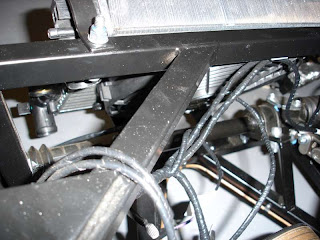
The radiator was mounted at angle for two reasons. The first, as I don't yet have the bodyshell on I don't know how much space I have to work with, so erred on the safe side. Second, if mounted vertically both the pipe openings clash with other things (steering rack and upper chassis rail).
The fan wiring will be connected once the wiring loom in the engine bay is properly routed and mounted.
Sunday 15 May 2011
Engine and Gearbox Fitted
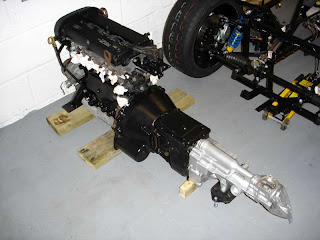
Engine and gearbox being fitted. Wooden blocks used in place of the engine rubbers to find the right position for drilling the holes. Despite checking and re-checking the engine and gearbox did end up a little further back than planned. Possibly due to the fact that one of the Tiger engine mounts does not sit flat with the plate on the chassis. When the engine rubber is in place this is squashed on one side to take up the difference.
Final result seems okay, there is some small amount of the propshaft splined tube showing outside of the rear of the gearbox, just not as much as expected. In a way this might be helpful. It will mean that the Rally Design gear lever remote ends up just that little bit futher towards the rear of the car - every bit counts here as the gear lever gets very close to the dashboard when this particular remote is used in the Avon.
Drilling the bolt holes for the gearbox mount was a bit of a challenge - getting the drill down inside the transmission tunnel, especially as I had already fixed one side to the chassis. The solution was to use an oversize hole at the top and then drill a correct size hole at the bottom, by drilling down at an angle.
Thanks to Pete for loan of the engine crane and Gary for help with the fitting, including use of his Avon as a reference for measurements.
Tuesday 10 May 2011
Joining the Engine and Gearbox
New clutch release bearing fitted to the clutch fork. Lubrication applied as instructed in the clutch kit.
Engine and gearbox fitted together. New cap head bolts, thread locked and torqued up to the correct amount.
Engine and gearbox fitted together. New cap head bolts, thread locked and torqued up to the correct amount.
With the Tiger ERA sump fitted the gearbox mounting holes in the lower crank case are no longer present. Only the upper five bolt holes can be used. Two dowels are still available to ensure gearbox alignment. Next job is to crane the engine into the rolling chassis and make good the engine mounts.
Flywheel and Clutch
To add the new ring gear to the Tiger lightened flywheel the former was put in a hot oven and the latter in the freezer. Once fitted the ring gear was held in place with weights until both had returned to room temperature.
Comparing old (Focus) and new lightened (Pinto) flywheels. On the scales the Focus weighs in at 9.8kg and the Pinto at 5.8kg. Hopefully this will give a good performance boost in terms of acceleration, along with a more responsive throttle response.
The flywheel bolts were shortened so that the same amount of thread (15mm) showed through the rear of the flywheel as in the original Focus installation (the lightened Pinto flywheel is thinner - no prizes there). All good so far. However, the edges of the bolts clash with the tapered edge of the flywheel. Also the socket fouls on the flywheel.
Plan B was to use another, original length, set of flywheel bolts and use washers as spacers. Two washers were needed for each bolt to compensate for the thickness of metal removed from the flywheel. The washers nearest the flywheel needed filing down (from 5mm to 3mm) on one edge. Okay, the edge was not there until I filed it!
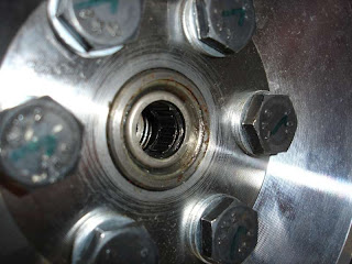
Flywheel bolts installed with thread lock. Each was marked to show that it had been torqued up to the correct value. In the centre is the spigot bearing fitted. Pushed in just flush with the outer edge. It would've gone in further, but here it should provide maximum support for the gearbox input shaft.
Fitting the clutch using an old borrowed gearbox input shaft as a centring tool (Thanks Pete). This made it very easy to get the perfect alignment of the clutch plate.
Thursday 5 May 2011
Tiger ERA Sump
Time to replace the tall original Focus sump with the shorter ERA sump from Tiger. On the later Black Top Zetec engine both the steel sump pan and the alloy lower crank case need to be removed. Here is the engine with just the sump pan removed. Visible is the plastic oil pick-up pipe. This cannot be shortened so will be replaced by a earlier steel pick-up pipe that has been modified by Tiger (chopped, shortened and welded).
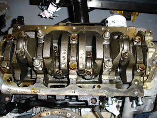
The lower crank case removed.
Four bolts in two of the main bearing end caps are replaced with Silver Top Zetec bolts that have a threaded stud on the top. Tubular steel spacers are added to allow the windage tray to be at the right height.
A similar recess was made on the ERA sump using a round file.
Four bolts in two of the main bearing end caps are replaced with Silver Top Zetec bolts that have a threaded stud on the top. Tubular steel spacers are added to allow the windage tray to be at the right height.
The windage tray, again from an earlier Silver Top Zetec, is bolted on to the four studs using thread-locked M8 nuts. The modified pick-up pipe is bolted on using a new gasket. This pipe is attached to one of the studs via a mounting bracket. Washers were used as spacers to get the right height (8-10mm from bottom of new sump). This was checked using a ball of Plasticine.
On trial fitting the ERA sump fouls with the oil pump housing. This means the sump bolt holes do not line up. A curved recess is present on the original lower crank case (seen lower left).
A similar recess was made on the ERA sump using a round file.
Sump mounted using a new gasket and the original bolts tightened to the specified torque.
Once the car is on the road I'll think about adding some baffles to the sump to prevent oil starvation when driven hard, e.g. on the track.
The next problem is one of the engine mountings. I had previously trimmed this to make if fit around the water pump housing. Now with the new sump on the engine mount hits the sump edge before being flush with the mounting holes cast in the engine block. If tightened in this state the engine mounts will 'push' the sump sideways and the large engine loads will be transmitted through the sump - not good. Next job then is to trim a little of the lower edge of the engine mount.
Subscribe to:
Posts (Atom)
