Showing posts with label Hammerite. Show all posts

Tuesday, 22 November 2011

Cycle Wings

After the bonnet the job I was least looking forward to was fitting the cycle wings.  It did indeed turn out to be quite involved.

First off I needed to clear the threads in the front uprights - these were rusty and also had some paint in them.  I hadn't realised when renewing the uprights that these threaded holes would be needed.  A second hand 8mm tap from a local tool shop did the job easily.

Spacer tubes need to be cut to mount the cycle wing vertical arms the correct distance from the tyres.  This is a bit of trial and error and I found it easiest to use washers to calculate the length prior to cutting the tubes.

With the stays mounted in the correct position I could start to fit the cycle wings themselves.  They don't just bolt on unfortunately.  The horizontal arms of the stays need to be bent up into the curvature of the cycle wings.  To work out how far to bend them I tried spacers of different thickness.  A couple of pencil rubbers turned out to be perfect for the job.


Then the stays were bent in the vice, ensuring that the upper part remained parallel with the tyre.  Due to the bending of the stays some of the powder coating flaked off.  Some Hammerite was applied to prevent rusting.


The cycle wings were then trial fitted using an axle stand as a height reference.  The current IVA manual states that the cycle wings must extend at least 50 degrees to the rear and 30 degrees to the front.  The rear was nearly 90 degrees so that was okay.  The front was harder to measure.  In the end the geometry of the wheel came to the rescue.  There are 12 spokes.  360 degrees divided by 12 equals 30 degrees per spoke.  With one spoke vertical I could easily determine that I had about 45 degrees coverage to the front.


A length of bicycle inner tube (700c x 23) was pulled over the horizontal arms to protect the fibreglass from the metal edges.  Holes were drilled in the cycle wings and stays and then dome head bolts used to secure them together.

19mm holes were drilled to accommodate the LED side repeaters.  I had to be careful here as it is quite close to the edge and I didn't want to split the cycle wing.  The repeaters are mounted by inserting the rubber collar into the hole and then pushing the light through, making sure the 'TOP" marking was uppermost.  Due to the curvature of the cycle wing shoulder the rubber did not want to sit fully flat with the (curved) surface.  A little persuasion from Mr Super Glue did the trick.


Finally, the wiring for the side repeaters was extended to reach the inside of the car.  This was cabled tied to the cycle wings stays and under the cycle wings cable tie mounts were attached using Grip Fill.  Before fitting the side repeaters I tested them on the car battery.  They are reassuringly bright.  One oddity is that the black lead is not negative, but positive!  White is negative.

In the end I am quite pleased with result, but the cycle wings are quite a lot of effort from start to finish.

Tuesday, 11 October 2011

Exhaust Fitted

Bracket made up to mount the silencer, painted with Hammerite and bolted through one of the steel chassis plates.

To fit the exhaust I used a high temperature silicon sealant (PRO SEAL RTV Silicone Instant Gasket RED 85g Hi-Temp) - it is flexible so won't crumble like exhaust paste and clog the catalyst.  Also it is supposed to be safe for use on lamda sensors.


Next to do is installation of the lamda sensor.

Friday, 20 May 2011

Polo Radiator Fitted

Some simple brackets made up from 5mm steel strip.  B&Q had exactly the right piece of steel available from which to cut these.  The brackets were given a quick couple of coats of Hammerite.


Lightweight (tinfoil and plastic) Polo radiator fitted and fan mounted.  I decided to go for a 'pull' type fan in the end. This leaves the front of the radiator free for fitting an oil cooler later - no plans at the moment though.


The 12 inch fan fits in very nicely behind the radiator.


The radiator was mounted at angle for two reasons.  The first, as I don't yet have the bodyshell on I don't know how much space I have to work with, so erred on the safe side.  Second, if mounted vertically both the pipe openings clash with other things (steering rack and upper chassis rail).


The fan wiring will be connected once the wiring loom in the engine bay is properly routed and mounted.

Monday, 4 April 2011

Gearbox and Bell Housing

Here is the Type-9 gearbox and bell housing as bought secondhand from ebay.


Before separating the the two the clutch release fork was removed.  To do so required that the clutch release bearing be removed.  The bearing was destroyed during the process.  No problem as a new one is provided in the new Pinto clutch kit.  Once the gearbox and bell housing were separated they cleaned with lots of rags and lots of white spirit.

I attempted to remove the reverse stop from the gearbox, but in the end I gave up as it did not seem to want to move and I did not want to damage the gearbox housing.  I tried my Rally Design remote and it functions fine with the original reverse stop still in place in the gearbox.  There is a replacement reverse stop in the gear lever end of the remote.


Bell housing cleaned and degreased, ready for painting with Hammerite.


The oil seals on the input and output shafts were replaced.  The sleeve for the clutch release bearing has to be removed to change the input shaft oil seal.  Upon refitting a new cork gasket is fitted.

Here is the gearbox, repainted, with new oil seals.  The only oil seal that I could not change was the one on the speedo drive shaft.  I removed the side access plate, but when I looked inside you can removed the speedo drive shaft, but it looks like you can't get to the oil seal on the other side without completely dismantling the gearbox.  Something I don't plan on doing!  Fingers crossed this tiny oil seal doesn't let me down once the gearbox is in the car.


A new gasket was fitted between gearbox and bell housing prior to mating the two.  If this is not done the gearbox will empty its oil via the hole that the gear selector rod exits through.


Gearbox and bell housing bolted back together, torqued up as per the Hayne's manual.  The clutch release fork will be reinstalled, along with the new clutch release bearing, at a later stage.


New gearbox mount was trial fitted prior to putting the whole assembly aside, to wait for the engine to be tidied up.


Sunday, 27 March 2011

Front Suspension, Hubs and Brakes

Here are the very sorry looking Cortina uprights, discs and calipers bought from ebay.


These were dismantled and the discs discarded.  The uprights just needed the rust removing with a wire brush attachment in the drill before they could be masked and painted with Hammerite.


After cleaning the hubs I attempted to remove the outer bearing races.  Unlike the rears, which were easy to remove, these would not shift.  The task made harder by the fact that they need to be pushed from the opposite site, i.e. a tool was needed to get through the centre hole of the hub, from the other side.  In the end it looked my efforts were going to risk damaging the hubs, so I admitted defeat and took them down to my local engineering shop.  They removed the races the same afternoon for a small amount of beer tokens.

Here is one of the hubs with the new outer bearing races fitted and the wheel studs repaced for longer versions.  These are to accommodate the alloy wheels instead of steel.


The hubs were then painted.  After fitting new discs the centre of the disc was masked for painting, the part that is not swept by the brake pads.  The idea here is to prevent this from going rusty and looking unsightly behind the alloy wheels.  Time will tell if this area gets too hot for normal Hammerite paint.


The bolts that fix the discs to the Cortina hubs normally have locking tabs fitted.  Two were missing.  I fabricated two new ones from some thin sheet steel by tracing round one of the originals, cutting with a jigsaw and then finally filing in the vice, with the new and old clamped together as a guide.  Spot the difference?


Hub and disc ready for fitting.


Upright fitted to car.  Upper ball joint not fully torqued until the camber has been set.  This will be done at a later stage.


Hub assembly fitted to upright, using a new wheel bearing kit.  This was then torqued to the correct amount, as per the Cortina Haynes manual.  As one of the hub grease caps was missing I bought two new aluminimum ones from Rally Design.  They were not cheap, but are very well made.  Shame they won't be seen behind the centre of the alloy wheels.


I entertained the idea of renewing the calipers, but in the end it seemed too much effort when new ones can be bought from Rally Design for a very competitve price.  The old ones will go back on ebay.  Here are the new calipers fitted, along with a set of new EBC Green Stuff pads.


All complete, barring the fitting of the brake flexi hose.  This can only be done once the body shell is on.

Monday, 21 February 2011

Futher Modifcation of Suspension Uprights

The front and rear dampers were fouling the brackets on the rear uprights as well as the lower front wishbones.  The 'corners' were filed round and then painted with Hammerite.  Care was taken to remove the minimum amount of metal, so as not to damage the structural integrity of these components.


Saturday, 29 January 2011

Wheel cylinders and brake shoes fitted

New wheel cylinders were sourced from the local motor factors. These turned out to be very reasonably priced. After looking through the catalogue it was determined that my rear brakes are from a 1.8 or 2.0 Sierra estate car. This seems to tally with the fact that these are the bigger, nine inch, drums. The wheel cylinders were given a couple of coats of Hammerite to prevent rusting.

After that the new brake shoes were fitted. These were bought from EBC's online shop. Free next day delivery too.

The brake drums will be fitted later, after the hand brake cables are attached.

Saturday, 22 January 2011

Longer Wheel Studs

The existing wheel studs are very short - suitable for the original Sierra steel wheels, but not the alloy wheels that will be fitted to the finished Avon. The old studs were removed using a bench press and the 41mm hub nut socket (yes, it has come in handy many times already, not just for the hub nuts!)


After painting the drive flange with black Hammerite satin longer wheel studs (from Tiger) were installed. Again, using the bench press. Here is the finished product with old and new studs for comparison.


If, after trying the alloy wheels, these turn out to be too long they can be cut down.

If no bench press is available, the wheel studs can be removed with a large hammer, but really this would be easier with the drive flange still on the donor car. The new longer studs could then be pulled through by tightening up the wheel nuts. Not sure though if this would require too much pressure to be put on the alloys.

Wednesday, 5 January 2011

Rear Suspension Upright Modification

The Sierra donor brake back plates do not fit flush with the Tiger provided rear suspension uprights. The extremeties of the flat angled plate foul with the curved bulges on the back face of the brake back plates.

A small amount of metal has to be removed from two places on the rear uprights. The areas to be removed can be marked out with a permanent marker pen with the back plate pressed against the upright. Then an angle grinder with a thick metal cutting disc can be used to remove the offending portion of metal. Removing small amounts at a time and repeatedly trial fitting ensured that only the minimum of metal was cut away. Thereby ensuring minimal reduction in the structural integrity of the upright.

Here is a view of one of the uprights after surgery. The bear metal surfaces will be painted with smooth black hammerite prior to fitting of the brake back plate.

Wednesday, 22 December 2010

Driveshaft Renewal

The driveshafts had previously been removed from the Sierra rear beam and set aside. Soon these will be needed for assembly onto the car. However, first they need to be renewed.

First the internal metal surfaces were masked in tape, i.e. those which go inside the final drive and the rear hub. Then a wire brush attachment in a drill was used to remove all loose rust. After degreasing, a couple of coats of smooth Hammerite were added.

The driveshaft gaiters were most likely the original from when Ford built the Sierra about 20 years ago. It seemed prudent to change these while the driveshafts were off the car. I used a 'slide-a-boot' kit for each. These were bought from eBay and can be used without having to dismantle the drive shaft.

First the old gaiter is removed. The cone is cut down to length and covered in the lubricant provided. The cone is placed over the end of the draftshaft and the gaiter is pulled over the cone on to the driveshaft. The gaiter needs to be pulled inside out beforehand. The gaiter is now pulled the back the right way, grease packed into the CV joint and finally the cable ties used to secure the two ends of the gaiter. The cable ties were used in preference to the metal bands as these were difficult to get tight.

Below the finished driveshaft, painted, gaiters replaced and ready for installation on the car. Same process for the other driveshaft.

Sunday, 5 December 2010

Final Drive

Here is the final drive (differential) as it was removed from the donor Sierra rear beam. Quite sorry looking, with some oil on the case where the original oil seals had started to fail.


First job was to remove the nut on the prop shaft flange. Then the flange itself could be removed with a three legged bearing puller. The three oil seals were removed by pulling very hard with adjustable grips, being careful not to damage the inner surface of the final drive unit.

After spraying with water soluble degreaser the final drive unit was steam cleaned using a domestic steam cleaner and a small wire brush drill attachment. The result was very good, with all oil and dirt removed. During the cleaning the openings were covered to prevent debris, degreaser or water getting into the internals. A couple of coats of Hammerite special metals primer were added. This ensured the silver top coat would have good adhesion.


The final drive unit was then given two coats of smooth silver Hammerite. The prop shaft flange as well as the nuts on the rear of the unit were painted in black Hammerite. Then the new oils seals were installed, using a suitable drift and hammer. Camberley Auto Factors no longer stock oil seals or other parts for the Sierra, but eBay came to my rescue (yet again).

Here is the final drive mounted in the chassis using the new bolts and nyloc nuts provided by Tiger.

Tuesday, 9 November 2010

Steering Rack

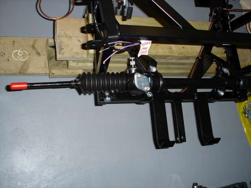
Time to mount the Tiger quick steering rack. This is achieved by using the two clamps, each with a rubber insert. The clamps, as supplied by Tiger, are nothing more than bent pieces of steel. The rubbers each have a split underneath to allow it to be passed around the steering rack.


First the clamps had to be painted with black Hammerite and then measured for drilling the bolt holes. With the holes drilled it was simply a case of bolting through, while making sure that the rubbers were in the right position on the steering rack iteself.