Saturday 29 January 2011

Wheel cylinders and brake shoes fitted

New wheel cylinders were sourced from the local motor factors. These turned out to be very reasonably priced. After looking through the catalogue it was determined that my rear brakes are from a 1.8 or 2.0 Sierra estate car. This seems to tally with the fact that these are the bigger, nine inch, drums. The wheel cylinders were given a couple of coats of Hammerite to prevent rusting.

After that the new brake shoes were fitted. These were bought from EBC's online shop. Free next day delivery too.

The brake drums will be fitted later, after the hand brake cables are attached.

Monday 24 January 2011

Tightening the Hub Nuts

With the drive flange fitted it was time to fit new a new hub nut. Most torque wrenches do not go up to the level required (about 260 ft/lb). Instead I used an approximation of my weight multiplied by the correct lever arm. I measured the right length along the breaker bar (14 inches) and then applied my full weight at that point, making sure that the car was adequately supported. The process will be repeated on the other driveshaft.

Sunday 23 January 2011

Fitting New Rear Wheel Bearings

I got a bearing kit (code BRT990) from my local motor factors. This has two bearings, two grease seals and two hub nuts (one left hand thread and one right).

I basically followed the Haynes manual. The part I had a problem with was the fitting of the outer grease seal. To get a better purchase I fitted the drive shaft to the car first (by bolting the hub carrier, through the brake back plate, to the upright). Using one of the old grease seals and the trusty 41mm socket the new grease seal could be tapped into place.

The bolts mounting the hub carrier to the upright were tightened up to the torque specified in the Haynes manual.

Saturday 22 January 2011

Assembly of Rear Suspension

The wishbones were all fitted with the 'weld marks' to the rear of the car. You would then expect the damper/spring to just bolt on between the chassis and the upper wish bone. If only it were that easy. The manufacturing tolerances or the design of the chassis jig don't allow this. Only after disassembly and reassembly in different sequences did I get it all to fit together. In the end I fitted the two wishbones to the upright, but not to the chassis. Then the damper/spring was fitted. Followed by the upper wishbone to chassis and finally the lower wishbone to chassis.

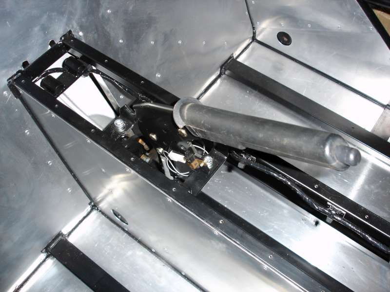
If you look sideways on you will see that the damper/spring fits, but only at a slight angle. In this view you can also see the spacer/crush tube that had to be cut to length and fitted between the two mounting lugs on the top of the upright.


Before fitting all the washers and nuts I followed Jim Dudley's guidance for setting up the rear suspension geometry (camber). To do this the shorter front dampers were installed on the rear (yes more disassembly and reassembly). The shorter front dampers allow the suspesion to hang in the position it will be in when the weight is on the wheels. With the car level on the floor a 1 metre length of square tube was clamped vertically to the upright and then a 900mm spirit level used to determine +1 degrees camber from the vertical. Using the small angle approximation it was detemined that a delflection of 13.5mm was required. This is for road use, more camber would be needed for track use. The rose joints on the lower wishbones were screwed in and out until the required deflection was maintained.

With the rear dampers/springs refitted all nyloc nuts and washers were fitted. Washers were fitted either side of the lower wishbone rosejoints. The nuts were kept loose and will be fully tightened when the cars weight is on the wheels.

Longer Wheel Studs

The existing wheel studs are very short - suitable for the original Sierra steel wheels, but not the alloy wheels that will be fitted to the finished Avon. The old studs were removed using a bench press and the 41mm hub nut socket (yes, it has come in handy many times already, not just for the hub nuts!)


After painting the drive flange with black Hammerite satin longer wheel studs (from Tiger) were installed. Again, using the bench press. Here is the finished product with old and new studs for comparison.


If, after trying the alloy wheels, these turn out to be too long they can be cut down.

If no bench press is available, the wheel studs can be removed with a large hammer, but really this would be easier with the drive flange still on the donor car. The new longer studs could then be pulled through by tightening up the wheel nuts. Not sure though if this would require too much pressure to be put on the alloys.

Tuesday 11 January 2011

Handbrake Lever Mounted

After measuring up and drilling two holes, the handbrake lever was mounted using 8mm socket cap head bolts, secured with nyloc nuts underneath.


I even connected up the wire for the handbrake light switch. Its not connected to anything at the other end, but it felt good to wire in the first component!

Sunday 9 January 2011

Non-slip Pedals

The Tiger floor mounted pedals come with rubber covers, the standard type that are fitted in production cars. However, these are a bit bulky for the restricted space in the drivers footwell. I had some left over skateboard grip tape from another project. I cut pieces and applied them to the brake and clutch pedals. Not sure how durable this will be in use, but it seems fairly tough stuff. The throttle pedal was left as smooth powercoated metal. This will allow easy variations to the throttle settting.

Wednesday 5 January 2011

Rear Suspension Upright Modification

The Sierra donor brake back plates do not fit flush with the Tiger provided rear suspension uprights. The extremeties of the flat angled plate foul with the curved bulges on the back face of the brake back plates.

A small amount of metal has to be removed from two places on the rear uprights. The areas to be removed can be marked out with a permanent marker pen with the back plate pressed against the upright. Then an angle grinder with a thick metal cutting disc can be used to remove the offending portion of metal. Removing small amounts at a time and repeatedly trial fitting ensured that only the minimum of metal was cut away. Thereby ensuring minimal reduction in the structural integrity of the upright.

Here is a view of one of the uprights after surgery. The bear metal surfaces will be painted with smooth black hammerite prior to fitting of the brake back plate.

Rear Wheel Bearing Removal

With the hub nut removed it is fairly easy to use a puller to remove the drive flange. After this the driveshaft can be removed from the hub carrier. Then the bearing all seals can be pulled out with a pair of mole grips, being careful not to damage the inner surfaces of the rear hub carrier. Once the oil seals are out the tapered roller bearings just drop out.

The harder part is removing the outer bearing races from inside the hub carrier. These bearings are back-to-back and therefore it is not possible to push them out with a press. Neither is it easy to pull them out with a puller - there is not enough surface to get a grip on. Perhaps a blind bearing puller might work, but these are very expensive.

In the end I fashioned a simple soft metal drift from a scrap brass ball valve arm - sourced from a friendly plumber. This improvised drift, teamed up with a normal claw hammer, was used to drive the outer faces from within the hub carrier. After each hit the hub carrier was rotated 90 degrees. This helped ensure the race came out straight and did not get jammed at an angle. The second race was even easier as there was more of its rear surface visible to use the drift on.