Wednesday, 5 January 2011

Rear Wheel Bearing Removal

With the hub nut removed it is fairly easy to use a puller to remove the drive flange. After this the driveshaft can be removed from the hub carrier. Then the bearing all seals can be pulled out with a pair of mole grips, being careful not to damage the inner surfaces of the rear hub carrier. Once the oil seals are out the tapered roller bearings just drop out.

The harder part is removing the outer bearing races from inside the hub carrier. These bearings are back-to-back and therefore it is not possible to push them out with a press. Neither is it easy to pull them out with a puller - there is not enough surface to get a grip on. Perhaps a blind bearing puller might work, but these are very expensive.

In the end I fashioned a simple soft metal drift from a scrap brass ball valve arm - sourced from a friendly plumber. This improvised drift, teamed up with a normal claw hammer, was used to drive the outer faces from within the hub carrier. After each hit the hub carrier was rotated 90 degrees. This helped ensure the race came out straight and did not get jammed at an angle. The second race was even easier as there was more of its rear surface visible to use the drift on.

Wednesday, 22 December 2010

Driveshaft Renewal

The driveshafts had previously been removed from the Sierra rear beam and set aside. Soon these will be needed for assembly onto the car. However, first they need to be renewed.

First the internal metal surfaces were masked in tape, i.e. those which go inside the final drive and the rear hub. Then a wire brush attachment in a drill was used to remove all loose rust. After degreasing, a couple of coats of smooth Hammerite were added.

The driveshaft gaiters were most likely the original from when Ford built the Sierra about 20 years ago. It seemed prudent to change these while the driveshafts were off the car. I used a 'slide-a-boot' kit for each. These were bought from eBay and can be used without having to dismantle the drive shaft.

First the old gaiter is removed. The cone is cut down to length and covered in the lubricant provided. The cone is placed over the end of the draftshaft and the gaiter is pulled over the cone on to the driveshaft. The gaiter needs to be pulled inside out beforehand. The gaiter is now pulled the back the right way, grease packed into the CV joint and finally the cable ties used to secure the two ends of the gaiter. The cable ties were used in preference to the metal bands as these were difficult to get tight.

Below the finished driveshaft, painted, gaiters replaced and ready for installation on the car. Same process for the other driveshaft.

Sunday, 5 December 2010

Final Drive

Here is the final drive (differential) as it was removed from the donor Sierra rear beam. Quite sorry looking, with some oil on the case where the original oil seals had started to fail.


First job was to remove the nut on the prop shaft flange. Then the flange itself could be removed with a three legged bearing puller. The three oil seals were removed by pulling very hard with adjustable grips, being careful not to damage the inner surface of the final drive unit.

After spraying with water soluble degreaser the final drive unit was steam cleaned using a domestic steam cleaner and a small wire brush drill attachment. The result was very good, with all oil and dirt removed. During the cleaning the openings were covered to prevent debris, degreaser or water getting into the internals. A couple of coats of Hammerite special metals primer were added. This ensured the silver top coat would have good adhesion.


The final drive unit was then given two coats of smooth silver Hammerite. The prop shaft flange as well as the nuts on the rear of the unit were painted in black Hammerite. Then the new oils seals were installed, using a suitable drift and hammer. Camberley Auto Factors no longer stock oil seals or other parts for the Sierra, but eBay came to my rescue (yet again).

Here is the final drive mounted in the chassis using the new bolts and nyloc nuts provided by Tiger.

Wednesday, 17 November 2010

Steering column (upper and lower)

Two 12mm holes were drilled in the upper steering column mounting brackets. These were drilled towards the top to allow maximum leg room for the driver. The steering column is adjustable so it will be possible to lower it if required.


Sturdy 12mm socket head bolts were used to securely mount the upper steering column. Initially the grey plastic bush at the lower end of the upper steering column was chafing on the chassis mounted cylindrical bracket (tube). To minimise this I used a file to smooth the edge of the tube - removing a hard lip of powder coat and slightly radiusing the edge. Finally a smear of grease was added to the inside of the tube prior to assembly.


The lower steering column simply bolted in three places: to the triangular tube at the bottom of the upper steering column, the steering rack, and in the middle the rose joint bolts to one of the side chassis tubes. This rose joint mounting was left loose as it may need to be removed to install the engine. When it is ready for final assembly a thread lock solution will be used.

Tuesday, 9 November 2010

Steering Rack

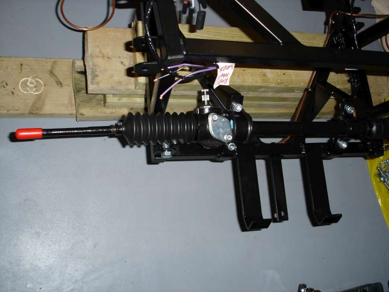
Time to mount the Tiger quick steering rack. This is achieved by using the two clamps, each with a rubber insert. The clamps, as supplied by Tiger, are nothing more than bent pieces of steel. The rubbers each have a split underneath to allow it to be passed around the steering rack.


First the clamps had to be painted with black Hammerite and then measured for drilling the bolt holes. With the holes drilled it was simply a case of bolting through, while making sure that the rubbers were in the right position on the steering rack iteself.

Friday, 5 November 2010

Wiring Loom

When you open the Tiger provided wiring loom it can look a bit daunting. The fuses and relays are obviously on the branch that comes up through the battery tray, but what about the rest? Finding which was the front and which was the back was achieved by identifying the large black alternator plug. Also, the wider double brown wires connect to the starter motor.

With the loom fed through the transmission tunnel the next step was to cut a hole in the battery tray to take the rubber gromit which is already on the loom. To cut the hole I used my trusty hole saw with a 41mm blade. Overall this work well, but like drilling the holes in the aluminimum panesl for the seat belt bolts, the teeth did tend to snag. It was a bit easier on the battery tray as the aluminium is thicker. Next time I think I will use a step drill for cutting circular holes through the aluminium panels.


Next it was time to start attaching the loom to the chassis. For this I used cable ties, cable tie mounts and rivets. The ties and mounts from Screwfix. Once the loom was attached along the inside of the transmission tunnel I then moved on to do the rear and finally the engine bay.


To identify each of the wires I used a number of wiring diagrams: the ones in 'the book', plus a couple sourced from the internet. None fully matched the actual colour coding and make up of my Tiger wiring loom, but by a process of elimination I worked out what each wire is for. I also took the opportunity to label each wire as I went. This should make connecting the wiring loom to the various items later on that much easier and quicker.

Monday, 1 November 2010

Fuel lines fitted

I've now finished fitting the copper fuel lines. As the engine will be fuel injected there are two lines: feed and return. At a later stage the ends will be terminated with fittings allowing connection of the relevant fuel hoses. On to the wiring loom next...